
Given that the power & RPM that are imposed upon the shaft are known, then the torque transmitted will be:
| T = HP×7119 | or | KW×9542 Nm |
| RPM | RPM |
This torque has to be effected by consideration of joint bearing life required, operating angle & application conditions.
The graphs D, E & F for the 3 different joint designs are based on a B10 bearing life of 5,000 hours and joint angle of 3 degrees.
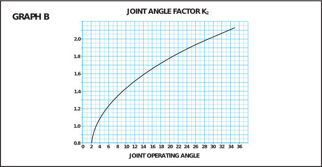
Graphs A & B give the appropriate factors for greater life and larger angle. A further factor should be included if there is direct connection of the shaft to prime movers as given in table C.

| PRIME MOVER | K3 | |
|---|---|---|
| Electric Motor | (4cyl. and more) | 1,00 |
| Gasoline engine | (4cyl. and more) | 1,25 |
| Diesel engine | (4cyl. and more) | 1,30 |
Using Te & RPM as the co-ordinates on either of the following graphs D, E or F locate the application position in relation to the series lines. If this should be between two series lines, select the upper one.